In the world of industrial automation, compressed air is often referred to as the “fourth utility.” However, raw compressed air from a compressor is rarely ready for immediate use. It is typically hot, dirty, and wet—factors that can lead to premature equipment failure and costly downtime. This is where an air preparation unit, commonly known as an FRL unit (Filter, Regulator, Lubricator), becomes indispensable. But how does an air preparation unit work to transform raw air into a high-quality power source? This guide explores the intricate mechanics, industry standards, and essential components that ensure your pneumatic systems operate at peak efficiency.
What is an Air Preparation Unit and Why is it Essential?
An air preparation unit is a modular system designed to treat compressed air before it reaches downstream pneumatic components like valves, cylinders, and air tools. Its primary mission is to ensure the air is clean, stable in pressure, and properly lubricated. Without this critical stage, contaminants such as rust, scale, and moisture can cause internal corrosion, while fluctuating pressures can lead to inconsistent machine performance.
Why Do Pneumatic Systems Require Treated Air?
The reliability of any pneumatic circuit depends on the quality of the air flowing through it. According to the ISO 8573-1 international standard, compressed air quality is categorized based on the concentration of solid particles, water, and oil. An effective air preparation strategy helps facilities achieve specific air purity classes, thereby extending the lifespan of expensive machinery and reducing maintenance costs.
“Compressed air is a vital energy source, but its quality directly impacts the efficiency and longevity of pneumatic components. Proper air preparation is not an option; it is a necessity for modern industrial operations.” — Industry Best Practices for Pneumatic Systems
How Does the Filtration Process Remove Contaminants?
The first stage of any FRL system is the air filter. Its role is to remove solid particles and liquid moisture that could damage sensitive internal seals. But how does a pneumatic filter work to achieve such high levels of purity?
The Mechanics of Centrifugal and Barrier Filtration
When high-pressure air enters the filter housing, it is directed through a set of guide vanes that create a powerful swirling motion. This centrifugal action flings heavier contaminants—such as water droplets and large scale—against the inner walls of the bowl. These pollutants then settle into the “quiet zone” at the bottom, where they can be drained manually or automatically.
Following the centrifugal stage, the air passes through a filter element, typically made of sintered bronze or high-efficiency fibers. This element acts as a physical barrier, trapping smaller particles based on its micron rating. Common industrial filters range from 40 microns for general-purpose use to 5 microns for more sensitive applications.
|
Feature
|
Centrifugal Stage
|
Barrier Filtration Stage
|
|
Primary Target
|
Bulk water, oil droplets, large debris
|
Fine dust, rust particles, aerosols
|
|
Mechanism
|
Swirling motion and gravity
|
Physical trapping by porous media
|
|
Maintenance
|
Regular draining of the bowl
|
Periodic replacement of the element
|
How Does a Pressure Regulator Maintain System Stability?
Once the air is clean, it must be delivered at a consistent pressure. Air compressors often cycle between high and low pressures, and the main header line may experience “surges” as other machines start or stop. How does a pressure regulator work to provide a steady output despite these fluctuations?
The Role of the Diaphragm and Poppet Valve
The heart of a pneumatic pressure regulator is a flexible diaphragm connected to a poppet valve. The user sets the desired output pressure by turning an adjustment knob, which compresses a heavy-duty spring against the diaphragm.
1.Pressure Sensing: The diaphragm “senses” the downstream pressure.
2.Valve Adjustment: If the downstream pressure drops (e.g., a cylinder starts moving), the spring pushes the diaphragm down, opening the poppet valve to allow more air through.
3.Automatic Balancing: Once the set pressure is reached, the air pressure underneath the diaphragm overcomes the spring force, allowing the poppet valve to close or modulate.
This continuous feedback loop ensures that your tools receive exactly the pressure they need—no more, no less—optimizing energy consumption and preventing over-pressurization damage.
How Does a Lubricator Protect Your Pneumatic Components?
The final stage of an air preparation unit is the lubricator. While many modern pneumatic components are “pre-lubricated” or “oil-free,” many heavy-duty cylinders, air motors, and high-speed valves still require a fine mist of oil to reduce friction and wear. But how does a pneumatic lubricator work to add oil to a high-velocity air stream?
The Venturi Effect and Oil Atomization
A pneumatic lubricator operates on the Venturi principle. As the clean, regulated air passes through a constricted section of the lubricator, its velocity increases, causing a localized drop in pressure. This pressure differential draws oil from the reservoir up through a pickup tube and into a sight dome.
Inside the sight dome, the oil is atomized into a “micro-mist”—a fine aerosol of oil particles that can travel long distances through the air lines without settling. This ensures that even the most remote components in your pneumatic circuit receive the necessary lubrication.
•Adjustable Drip Rate: Most lubricators feature a manual adjustment screw that allows the operator to set the exact number of drops per minute.
•Micro-Mist Technology: High-performance lubricators can create oil particles as small as 2 microns, which stay suspended in the air stream more effectively than standard oil fog.
“The Venturi effect is the cornerstone of efficient pneumatic lubrication. By leveraging fluid dynamics, we can deliver precise amounts of oil to critical moving parts without manual intervention.” — Fluid Power Society Technical Bulletin
What are the Step-by-Step Stages of Air Preparation?
To understand the complete workflow, let’s look at the step-by-step process of how an air preparation unit works from inlet to outlet. This integrated approach is what makes the FRL unit so effective.
1.Inlet Port: High-pressure, contaminated air enters the unit from the main compressor line.
2.Centrifugal Separation: Guide vanes in the filter bowl create a vortex, spinning out bulk water and large debris.
3.Barrier Filtration: The air passes through a sintered element (e.g., 5μm or 40μm) to trap fine particles.
4.Pressure Sensing: The air enters the regulator, where a diaphragm senses the downstream pressure.
5.Pressure Reduction: The poppet valve modulates to maintain the user-defined set point (e.g., 90 PSI).
6.Oil Atomization: The regulated air passes through the lubricator’s venturi, drawing oil into the stream.
7.Outlet Port: Clean, stable, and lubricated air is delivered to the pneumatic system.
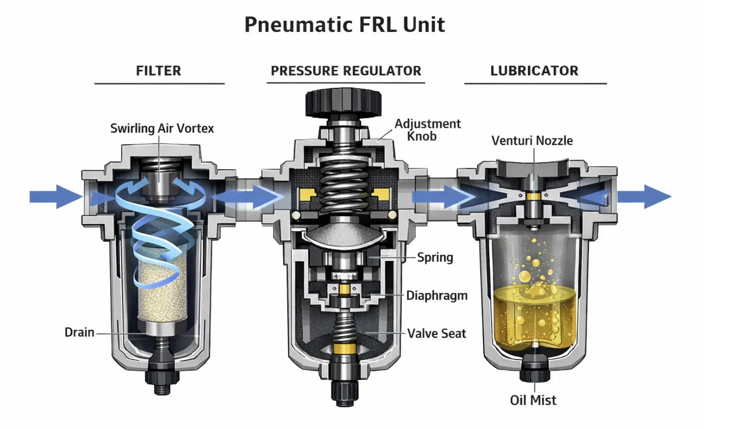
Figure 1: Internal mechanics and airflow path through a standard Filter-Regulator-Lubricator (FRL) unit.
What are the Benefits of Using an Air Preparation Unit?
Investing in a high-quality air preparation unit offers several long-term advantages for any industrial facility. By ensuring the air quality meets ISO 8573-1 standards, you can achieve:
•Extended Component Life: Clean, lubricated air reduces wear on seals and internal moving parts.
•Reduced Downtime: Preventing moisture and debris from entering the system minimizes the risk of sudden failures.
•Improved Machine Accuracy: Stable pressure ensures that pneumatic actuators move with consistent force and speed.
•Energy Efficiency: Regulating air to the minimum required pressure reduces the load on the air compressor, saving electricity.
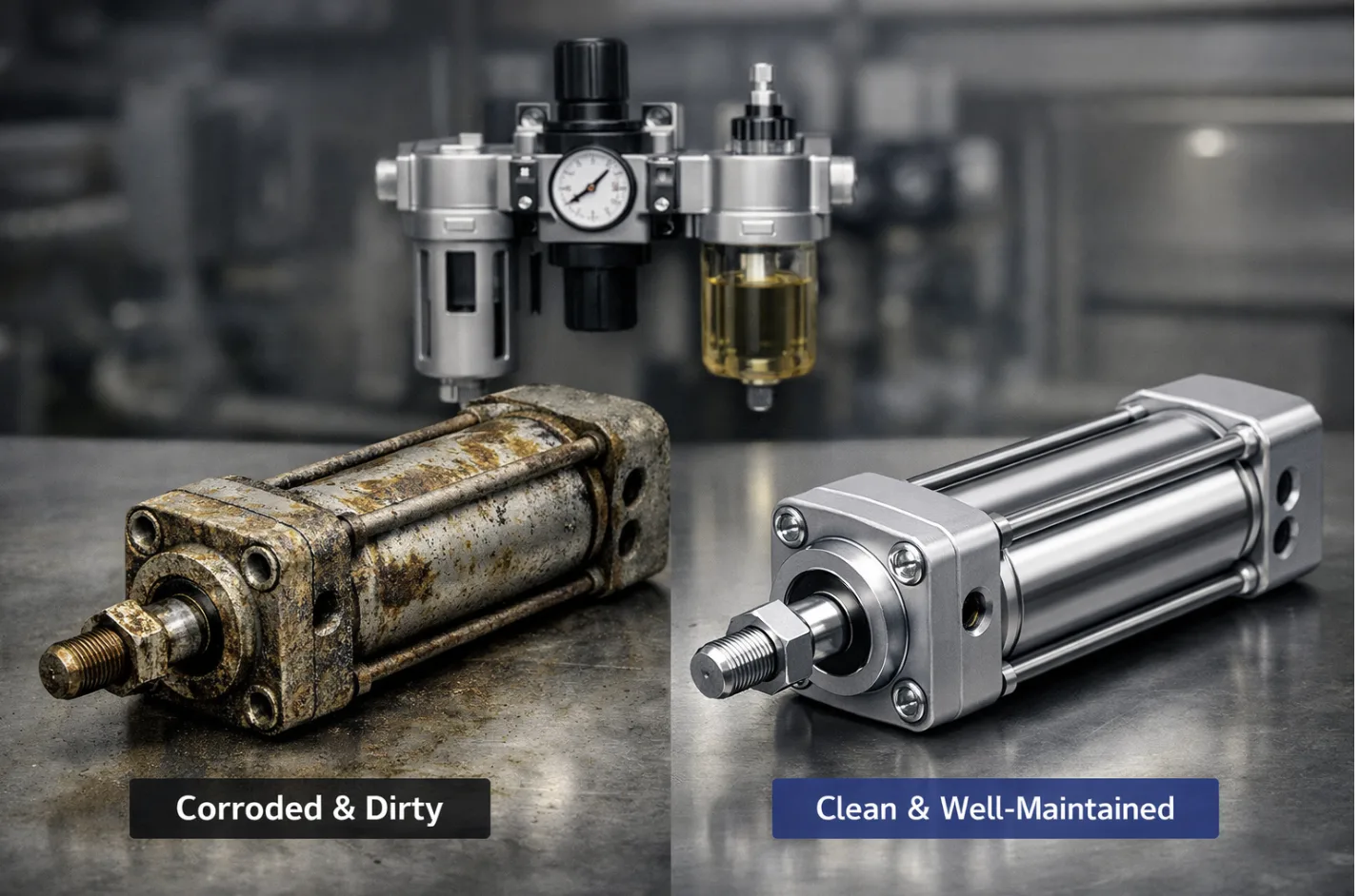
Figure 2: Visual comparison of a corroded pneumatic cylinder (left) versus a well-maintained component (right) protected by proper air preparation.
How to Select the Right Air Preparation Unit for Your System?
Choosing the correct FRL unit requires careful consideration of several factors. A unit that is too small will restrict airflow, while one that is too large may be an unnecessary expense.
|
Selection Factor
|
Description
|
Key Consideration
|
|
Flow Rate (SCFM)
|
The volume of air the unit can handle.
|
Must match or exceed the system’s peak demand.
|
|
Micron Rating
|
The size of particles the filter can trap.
|
5μm for sensitive valves; 40μm for general tools.
|
|
Pressure Range
|
The minimum and maximum regulated pressure.
|
Ensure the regulator can handle your specific set point.
|
|
Bowl Material
|
Polycarbonate, metal, or guarded bowls.
|
Metal bowls are required for high-pressure or chemical environments.
|
|
Drain Type
|
Manual, semi-automatic, or fully automatic.
|
Auto-drains are best for high-moisture environments.
|
How to Maintain Your Air Preparation Unit for Maximum Efficiency?
Regular maintenance is the key to ensuring your air preparation unit continues to work effectively. A neglected FRL unit can become a source of contamination itself.
The Essential Maintenance Checklist
1.Drain the Filter Bowl: If you have a manual drain, empty the bowl daily to prevent moisture from re-entering the air stream.
2.Replace the Filter Element: Most manufacturers recommend replacing the element every 6-12 months, or when the pressure drop across the filter exceeds 10 PSI.
3.Check the Lubricator Oil Level: Ensure the reservoir is filled with the correct grade of pneumatic oil (e.g., ISO VG 32).
4.Inspect the Regulator Diaphragm: Look for signs of wear or air leaks around the adjustment knob.
5.Monitor the Pressure Gauge: A fluctuating gauge may indicate a failing regulator or a clogged filter.
“A well-maintained FRL unit is the first line of defense for any pneumatic system. By following a simple maintenance schedule, you can prevent 90% of air-related machine failures.” — Industrial Maintenance Association Best Practices
FAQ: Common Questions About Air Preparation Units
What is the Difference Between a Filter and a Coalescing Filter?
A standard pneumatic filter removes solid particles and bulk water, while a coalescing filter is designed to remove fine oil aerosols and sub-micron particles. Coalescing filters are essential for high-purity applications like food processing or medical equipment.
Can I Use an Air Preparation Unit Without a Lubricator?
Yes, many modern pneumatic systems use “non-lube” components that do not require additional oil. In these cases, a Filter-Regulator (FR) combination unit is sufficient. However, if your system includes older air motors or heavy-duty cylinders, a lubricator is still necessary.
How Do I Know What Micron Rating I Need?
For general industrial tools and cylinders, a 40-micron filter is usually adequate. For sensitive proportional valves, air bearings, or precision instruments, a 5-micron filter or even a sub-micron coalescing filter is required to meet ISO 8573-1 standards.
Why is My Air Preparation Unit Leaking Air?
Air leaks are often caused by worn seals, a damaged regulator diaphragm, or a loose bowl. Regular inspection and the use of high-quality FRL unit spare parts can resolve most leakage issues.
How Often Should I Replace the Lubricator Oil?
You don’t “replace” the oil; you refill it as it is consumed. The rate of consumption depends on the drip rate setting and the volume of air flowing through the unit. Check the oil level weekly to ensure the system never runs dry.
Conclusion
Understanding how an air preparation unit works is the first step toward building a more reliable and efficient pneumatic system. By combining filtration, regulation, and lubrication, the FRL unit ensures that your equipment receives the high-quality air it needs to perform at its best. Whether you are operating a small workshop or a large-scale manufacturing facility, investing in the right air treatment technology will pay dividends in reduced maintenance and increased productivity.