What Is an FRL Unit in a Pneumatic System?
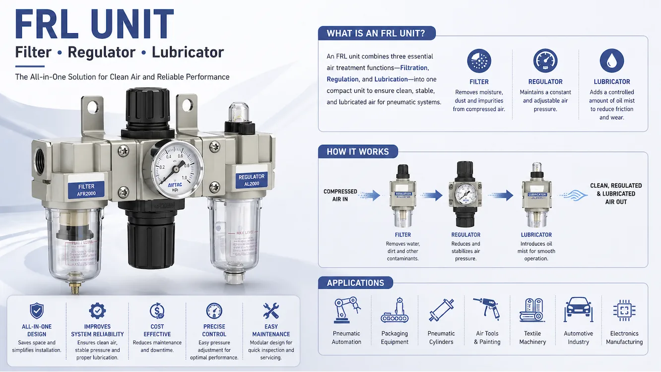
An FRL unit in a pneumatic system is a Filter, Regulator, and Lubricator assembly used to prepare compressed air before the air reaches valves, cylinders, actuators, or pneumatic tools. The core function of an FRL unit is simple: remove contamination, stabilize pressure, and add lubrication when lubrication is required. In many factories, poor air quality is one of the leading causes of pneumatic downtime because moisture, particles, and unstable pressure shorten component life. According to the U.S. Department of Energy compressed air guidance, inefficient air systems can waste a significant share of industrial electricity use. Use a properly sized FRL unit to reduce avoidable wear and air loss. External source: U.S. Department of Energy
For system integration, many buyers use pneumatic FRL unit solutions when designing machine air preparation stations.
Why FRL Units Matter for Compressed Air Efficiency
Compressed air leaving a compressor is rarely clean at point of use. Air may contain condensed water, rust from piping, compressor oil aerosol, and pressure fluctuation from demand cycles. ISO air quality standards recognize contamination control as a critical factor in industrial compressed air systems. If untreated air enters solenoid valves or cylinders, sticking seals and premature leakage become common failure modes.
An FRL unit solves three separate problems with one upstream device
Filter section removes water and particles
Regulator section controls downstream pressure
Lubricator section meters oil mist when required
Many maintenance teams install air filter regulator lubricator assemblies close to equipment to improve response consistency and simplify service intervals. External source: ISO Standards Organization
How Each FRL Component Works in Pneumatic Systems
Filter Function in FRL Unit
The filter is normally the first stage. A filter bowl separates liquid water and captures solid contaminants. Standard particulate ratings often range from 40 micron for general use to finer ratings for instrumentation service. Cleaner air protects valve spools, seals, and precision flow controls.
Regulator Function in FRL Unit
The regulator reduces and stabilizes outlet pressure. Many pneumatic devices operate best within a narrow pressure band. Excess pressure increases air consumption and accelerates seal wear. Stable pressure also improves cylinder repeatability.
Lubricator Function in FRL Unit
The lubricator adds controlled oil mist into airflow. Modern grease-packed cylinders may not need lubricated air, but older air tools and high-cycle rotary devices often still require lubrication. Use only when downstream equipment specifications allow it.
For modular layouts, many engineers select modular FRL components that allow separate replacement of filter, regulator, or lubricator sections.
FRL Unit Benefits for Industrial Pneumatic Equipment
| Benefit | Technical Impact | Operational Result |
|---|---|---|
|
Cleaner air |
Lower contamination load |
Fewer valve failures |
|
Stable pressure |
Controlled force output |
Better machine consistency |
|
Correct lubrication |
Reduced friction |
Longer tool life |
|
Local air prep |
Easier maintenance |
Faster service time |
A 1 psi pressure reduction across a large plant can create measurable annual energy savings depending on system load. Many compressed air audits focus first on leaks, then on pressure optimization. External source: Compressed Air Challenge
How to Choose the Right FRL Unit Size
Selecting the wrong FRL unit often causes pressure drop or underperformance. Use these criteria
Flow rate (SCFM or NL/min) required by equipment
Port size such as 1/4″, 3/8″, 1/2″
Operating pressure range
Filtration grade based on contamination risk
Drain type manual or automatic
Need for lubrication yes or no
A common mistake is choosing by thread size only. Flow capacity matters more than fitting size. For OEM projects, many sourcing teams compare industrial FRL regulator options with published Cv or flow curves.
Recommended FRL Installation Position
Install the FRL unit as close as practical to the machine inlet while keeping enough clearance for bowl service. The usual flow direction is:
Compressor → Dryer → Main Distribution → FRL Unit → Valve Manifold → Actuator
If multiple pressure zones exist, use dedicated regulators downstream. If one machine uses oil and another must stay oil-free, separate branches are preferred. OSHA workplace safety references also emphasize proper maintenance of compressed air equipment and safe pressure handling practices. External source: OSHA
Many machine builders use pneumatic air treatment units near each production cell for easier control.
FRL Maintenance Checklist for 2026 Operations
| Maintenance Item | Execution Frequency | Maintenance Purpose |
| Drain condensate | Weekly or by load | Prevent water carryover |
| Inspect bowl cracks | Monthly | Safety and leakage control |
| Verify pressure setpoint | Monthly | Stable machine output |
| Replace filter element | Per differential pressure or schedule | Maintain flow |
| Check oil level | Weekly if lubricated | Prevent dry running |
Unmaintained FRL units can create hidden pressure loss. Pressure loss forces compressors to run harder, increasing electricity cost and heat load. External source: U.S. DOE Advanced Manufacturing Office
Common FRL Unit Mistakes to Avoid
-
Installing a lubricator on oil-free instrument lines
-
Oversizing pressure settings “for safety margin”
-
Ignoring pressure drop across dirty filters
-
Using incompatible bowl materials near solvents
-
Mounting too far from critical equipment
-
Replacing only seals while leaving clogged elements in service
For replacement planning, buyers often compare FRL filter regulator replacement units by flow, thread, and maintenance access.
Key Conclusion: What Is FRL Unit in Pneumatic System?
An FRL unit is the air preparation center of a pneumatic system. The filter protects equipment from moisture and particles, the regulator stabilizes pressure, and the lubricator supports devices that need oil mist. Correct selection, correct installation, and routine maintenance usually deliver lower downtime, longer component life, and better compressed air efficiency.
FAQ
1. Is an FRL unit required for every pneumatic system?
No. Some systems need only a filter-regulator combination. Oil-free valves, clean-room equipment, and instrument air applications often avoid lubricators. Selection depends on downstream component requirements and air quality targets.
2. What pressure should an FRL regulator be set to?
Set regulator pressure to the lowest value that still meets machine performance needs. Higher pressure increases air consumption and wear. Use the equipment manual or actuator force calculations as the reference.
3. How often should an FRL filter element be replaced?
Replace by manufacturer schedule, pressure drop trend, or visible contamination. High humidity, poor piping condition, or heavy compressor oil carryover usually shortens filter life.
4. Can one FRL unit serve multiple machines?
Yes, but only if total flow demand, pressure stability, and lubrication compatibility are suitable. Separate FRL stations are often better when machines have different pressure or cleanliness needs.
5. What is the difference between FR and FRL units?
An FR unit includes only Filter and Regulator. An FRL unit adds Lubricator. FR units are common in modern oil-free automation lines, while FRL units remain common for air tools and legacy equipment.