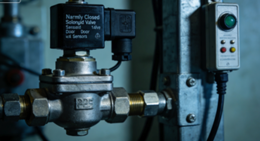
A normally closed Solenoid Valve is a crucial component in many fluid control systems. You might ask, what is a normally closed solenoid valve? Simply put, it blocks fluid flow when it is de-energized. This means no electrical current flows through it. When an electrical current applies, it allows fluid to pass through. The entire normally closed solenoid valve working principle relies on an electromagnetic coil and a movable plunger. Often called an NC solenoid valve, this type of valve, like a 2 way solenoid valve NC, provides reliable control. Understanding when to use normally closed solenoid valve types is key for efficient system design.
Key Takeaways
- A normally closed solenoid valve blocks fluid flow when it has no power. It opens when electricity flows to it.
- The valve uses an electromagnetic coil and a movable plunger. A spring keeps the valve closed when there is no power.
- When power is on, the coil creates a magnetic field. This field pulls the plunger up, which opens the valve and lets fluid flow.
- These valves are important in many systems. They control fluids in factories, air conditioners, and medical machines.
- Normally closed valves are safe. They close automatically if power fails, which stops fluid flow and prevents problems.
Understanding the De-energized State of a Normally Closed Solenoid Valve
When a normally closed Solenoid Valve is in its de-energized state, it performs its primary function: blocking fluid flow. This means no electrical current flows to the valve. Without power, the valve creates a physical barrier, ensuring no liquid or gas can pass through. This state is the default for the valve, providing a fail-safe mechanism in many systems.
Fluid Blockage in the De-energized State
In its de-energized condition, the valve effectively seals off the fluid path. A movable plunger or disc sits firmly against an opening, known as the orifice. This physical contact stops any fluid from moving through the valve. The material of the valve seat plays a vital role in this blockage. For example, manufacturers often use polypropylene (PP) for valve seats, especially in diaphragm pumps. This material works well for blocking fluids, depending on its compatibility with the fluid’s chemicals and any abrasive particles present. The tight seal prevents unwanted flow, maintaining system integrity until activation.
Role of Spring Force in Closure
A strong spring inside the valve plays a big part in keeping it closed. This spring constantly pushes the plunger down. It holds the plunger tightly against the valve’s opening, or orifice. This action keeps the flow path completely shut when the valve is de-energized. The spring’s force is crucial. It ensures the valve stays closed until an electrical signal tells it to open. For instance, the plunger return spring in a 2-way Normally Closed Solenoid Valve often uses stainless steel. This material provides the necessary strength and durability. The spring holds the plunger against the diaphragm, keeping the orifice closed and blocking the fluid. When power comes on, a magnetic field pulls the plunger up. This field must be stronger than the spring’s force. When the power goes off, the spring pushes the plunger back to close the valve again.
Pressure Differential for Sealing
The difference in pressure across the valve also helps with sealing. When fluid pressure builds up on one side, it can push the valve’s sealing components even tighter. This pressure differential helps maintain a secure seal. Fluid viscosity also affects how well the valve seals. Thicker fluids, with higher viscosity, often create a better seal. They are less likely to leak. However, thin fluids, with low viscosity, might leak more easily. For these thinner fluids, the valve might need a higher pressure difference to keep a good seal. This helps to stop any increased leakage. While fluid viscosity does not directly state the pressure differential for sealing, its impact on sealing efficiency and pressure drops indirectly dictates the pressure differential needed to maintain seal integrity. Higher viscosity fluids may require greater actuation forces for valves, which can be a factor in maintaining a sealed system under pressure.
Key Components of a Normally Closed Solenoid Valve
A normally closed Solenoid Valve relies on several key parts working together. Each component plays a vital role in its operation. Understanding these parts helps explain how the valve controls fluid flow.
The Solenoid Coil and Electromagnetism
The solenoid coil is the heart of the valve’s electrical operation. This coil creates the magnetic field. Manufacturers typically construct these coils from copper wire, wound around a hollow bobbin or tube. Enameled copper wire, with its insulating coating, serves as a core material for these coils. When electricity flows through the coil, it generates an electromagnetic field. This field is crucial for moving the valve’s internal parts.
The Plunger and Core Tube Assembly
The plunger is a movable metal rod inside the valve. It sits within the core tube assembly. This assembly guides the plunger’s movement. The plunger needs to be strong and respond well to magnetism. Common materials for plungers include:
- Steel and steel alloys: These are ferromagnetic, meaning they interact well with magnetic fields.
- High-grade steel alloy: This provides robust construction for continuous operation.
- Special alloy: This balances magnetic properties with wear resistance.
- Materials offering a good combination of magnetic response and mechanical strength.
The design of the core tube assembly significantly impacts how fast the valve opens and closes. Factors like the valve core’s material and the overall assembly structure influence these speeds. Some designs achieve opening and closing times under 1 millisecond.
Valve Body, Orifice, and Ports
The valve body houses all the internal components. Its material depends on the fluid it handles. For example:
- Cast iron works for water, oil, and gas.
- Stainless steel offers excellent corrosion resistance for harsh fluids.
- Plastics like PVC are good for corrosive fluids at lower pressures.
The orifice is the opening inside the valve where fluid passes. Its size directly impacts fluid flow. A larger orifice allows more fluid to flow with less pressure loss. Conversely, a smaller orifice restricts flow, which increases pressure drop. The flow rate is proportional to the square of the orifice diameter. This means doubling the orifice diameter increases the flow rate by four times. The valve also has ports, which are the entry and exit points for the fluid.
The mass flow rate (q_m) across an orifice can be described by the formula:
q_m = (C_d / sqrt(1 - β^4)) * ε * (π/4) * d^2 * sqrt(2 * ρ_1 * Δp)Where
dis the internal orifice diameter andΔpis the differential pressure.
The Energized State: Opening the Solenoid Valve
When you apply electrical power to a normally closed Solenoid Valve, it springs into action. This electrical current changes the valve’s state from closed to open, allowing fluid to flow. It’s a precise dance between electricity and mechanics.
Electromagnetic Field Generation and Plunger Movement
The moment electricity flows into the solenoid coil, it creates an electromagnetic field. Think of it like turning on an electromagnet. This field generates a magnetic force. This force pulls the plunger upwards, away from the valve’s seat. The strength of this magnetic field directly affects the force on the plunger. A stronger magnetic field means a greater force, which helps the plunger move quickly. This also provides a strong holding force to keep the plunger in its open position. Engineers constantly work to achieve a higher electromagnetic force on the plunger while keeping the valve compact and ensuring a fast response time.
AC solenoids, for example, initially draw a lot of power. This high power quickly activates the valve, creating strong peak currents to overcome hydraulic pressure, friction, and the spring tension that keeps it closed. Once open, the current and magnetic force needed to hold the plunger in place are much lower, which saves energy. However, AC solenoids experience a high inrush current at first, followed by a smaller holding current. If the plunger gets stuck during this initial high-current phase, the coil can quickly overheat and burn out. This usually points to a valve problem, like a jammed plunger, rather than a faulty coil itself. DC solenoids, on the other hand, use a consistent amount of power. This can lead to higher overall energy use because they often consume more current than necessary to simply keep the valve open, potentially wasting energy. While some DC designs use external circuits like capacitors to boost current for quick opening, this setup can still waste energy as heat.
Orifice Opening and Fluid Path Creation
As the electromagnetic force pulls the plunger up, it lifts away from the orifice. This action unblocks the fluid path. The orifice, which was previously sealed, now becomes an open channel. This creates a clear route for the fluid to move through the valve. The design of this orifice opening is critical. For instance, sharp-edged orifices tend to cause more cavitation, which is the formation of vapor bubbles in the fluid. Cavitation can damage the valve over time. Orifice thickness also significantly affects how and where cavitation starts. Some multi-holed designs, like those with four holes arranged alternately, can even eliminate cavitation under specific operating conditions. Inlet rounding also greatly influences cavitation behavior. An increase in the open flow area can increase the number of cavities and thus the intensity of cavitation. Researchers like Simpson et al. and Nohmi et al. have extensively studied how orifice geometry impacts these fluid dynamics.
Allowing Fluid Flow
With the orifice now open, fluid can freely pass from the inlet port to the outlet port. The valve effectively becomes a conduit, allowing the system to operate as intended. The maximum flow rate a valve can handle varies greatly depending on its design and size. For example, direct-operated solenoid valves can achieve flow rates between 8.4 and 24 liters per minute. Smaller 2-port proportional valves might handle 30 to 75 liters per minute, while larger ones can reach up to 225 liters per minute. Generally, Solenoid Valves can support maximum flow rates ranging from 80 to 4500 liters per minute, with Kv values (a measure of flow capacity) from 0 to 4 cubic meters per hour. This wide range means you can find a valve suitable for almost any fluid control application, from precise dosing to high-volume transfer.
Operational Cycle of a Normally Closed Solenoid Valve
A normally closed Solenoid Valve operates through a precise, repetitive cycle. This cycle involves switching between its closed (de-energized) and open (energized) states. This constant back-and-forth movement allows for accurate fluid control in many systems.
Transition from De-energized to Energized
The operational cycle begins when a control signal tells the valve to open. This signal can be a physical signal (PS) that rises above a certain threshold. It can also be an electrical current flowing through the relay winding that goes above an ‘energized’ current threshold. When this electrical current first flows into the solenoid coil, it creates an electromagnetic field. This field pulls the plunger upwards, opening the valve. This initial surge of power, known as inrush current, can be quite significant. It often ranges from 3 to 40 times the normal operating current. Factors like residual magnetic flux and the exact moment on the voltage wave when power applies influence this magnitude. This high current helps the valve overcome initial resistance and quickly open the fluid path.
Transition from Energized to De-energized
Once the system no longer needs fluid flow, the electrical power to the solenoid coil cuts off. Without the electrical current, the electromagnetic field collapses. The strong spring inside the valve immediately pushes the plunger back down. This action forces the plunger against the valve seat, sealing the orifice and blocking fluid flow once again. The valve returns to its default, normally closed state. This quick return ensures that fluid stops flowing precisely when needed, preventing waste or overfilling.
Continuous Fluid Control Mechanism
The valve repeats this cycle of energizing and de-energizing many times over its lifespan. This continuous operation provides reliable on/off fluid control. However, this constant activity means the valve experiences wear and tear. A normally closed solenoid valve can typically withstand 100,000 cycles or less before components may require replacement due to wear, especially without proper lubrication. Regular maintenance, generally every 6 to 12 months, helps extend its life.
Temperature also plays a big role in how well the valve performs over time. Solenoid coils generate heat when energized. Standard valves have low temperature rises, reaching a maximum of 144°F under continuous operation and 10% overvoltage. A maximum ambient temperature of 130°F is generally permissible for standard solenoid valves. Exceeding these limits can lead to dangerous failures. The maximum permissible fluid temperatures depend on the specific seal and body materials used. For example, FKM is standard for neutral fluids up to 194°F, while EPDM and PTFE handle higher temperatures. Higher fluid viscosities can also reduce the voltage tolerance range and extend response times. Latching solenoid valves can reduce power consumption and heat generation during long operational cycles, which helps with overall performance and longevity.
Applications of Normally Closed Solenoid Valves in Fluid Control
Normally closed valves are essential components across many industries. They provide reliable and precise control over fluid movement. Their ability to block flow by default makes them ideal for safety-critical systems and automated processes.
Industrial Automation Systems
In industrial automation, these valves play a critical role. They control the flow of air, water, oil, and other process fluids. Factories use them in pneumatic systems to operate cylinders and actuators. They also manage coolant lines for machinery. For example, a manufacturing plant uses these valves to ensure a specific amount of lubricant reaches a machine at the right time. This prevents equipment damage and maintains production efficiency. They also act as safety shut-off valves, immediately stopping fluid flow if a system fault occurs.
HVAC and Refrigeration Applications
Heating, ventilation, air conditioning (HVAC), and refrigeration systems widely use normally closed valves. They regulate the flow of refrigerants, water, and air. In an air conditioning unit, a valve might control the refrigerant entering the evaporator coil. This helps maintain the desired room temperature. In heating systems, they manage hot water or steam flow to radiators. These valves ensure efficient energy use and precise climate control in buildings.
Medical and Laboratory Equipment
Medical and laboratory equipment demand high precision and reliability. Normally closed valves are perfect for these applications. They control the flow of gases in ventilators and anesthesia machines. They also manage liquid reagents in diagnostic devices and analytical instruments. For instance, a lab instrument uses these valves to dispense exact amounts of chemicals for experiments. This prevents contamination and ensures accurate test results. Their dependable operation is crucial for patient safety and research integrity.
Normally closed valves are essential for precise fluid control. Their operation depends on electrical energy, magnetic force, and mechanical parts working together. These valves offer reliable on/off control, which is vital for many fluid control systems. They ensure systems function safely and efficiently. SENYA, for example, manufactures these crucial components, contributing to high-quality industrial applications.
FAQ
What is the main difference between a normally closed and a normally open solenoid valve?
A normally closed (NC) valve blocks fluid flow when it has no power. It opens when electricity flows to it. A normally open (NO) valve allows fluid flow when it has no power. It blocks flow when electricity flows to it.
Why should someone choose a normally closed solenoid valve?
People often choose normally closed valves for safety. They provide a fail-safe mechanism. If power fails, the valve automatically closes, stopping fluid flow. This prevents spills or uncontrolled processes, making systems safer and more reliable.
What happens to a normally closed valve if the power goes out?
If the power goes out, a normally closed solenoid valve immediately returns to its default state. This means the spring pushes the plunger down, and the valve closes. It stops all fluid flow, ensuring safety and preventing unwanted operations.
Can you use a normally closed valve for all types of fluids?
No, you cannot use a normally closed valve for all types of fluids. The valve’s materials, like the body and seals, must be compatible with the fluid. Always check the manufacturer’s specifications to ensure proper material compatibility for your specific application.