Choosing the correct Solenoid Valve is vital for system efficiency and reliability. Engineers consider several key factors. These include the specific medium, operational demands, valve design, and environmental conditions. Proper sizing and material compatibility prevent failures and optimize performance. Many ask, “What size solenoid valve do I need?” or “Which solenoid valve is best for water, air, oil, or steam?” Additionally, determining “What pressure rating should I select?” is crucial. When you buy solenoid valve, carefully evaluate these points for optimal selection.
Key Takeaways
- Choose the right solenoid valve by checking the fluid type, its temperature, and how clean or thick it is. This helps the valve work well and last longer.
- Match the valve’s materials, like the body and seals, to the chemicals in your system. This stops leaks and keeps the system safe.
- Understand the pressure and flow rate your system needs. This helps you pick the correct valve size and type, like direct or indirect acting valves.
- Consider the valve’s electrical needs, like voltage, and its protection from dust and water (IP rating). This ensures the valve works correctly and safely in its environment.
Understanding Medium Characteristics for Solenoid Valve Selection
Fluid Type and State
The type of fluid a system handles significantly impacts solenoid valve selection. Solenoid valves control the flow of liquid or gas. Industries use them for many different fluids. Common examples include water, compressed air, steam, and various petroleum by-products. They also manage heat transfer fluids, food product liquids, and corrosive liquids or gases. Fuel, inert gas, air, hydraulic fluid, and pressurized gas are other frequent applications. Engineers must know the fluid’s exact nature. This includes whether it is a liquid or a gas. This information guides material choices and valve design.
Temperature Range of the Medium
The medium’s temperature range is another critical factor. Extreme temperatures can affect valve materials and performance. Standard solenoid valves often handle media between 0°C and 80°C. This range suits most general industrial uses. However, some applications require different capabilities. Low-temperature environments, like cryogenic systems, need valves that operate as low as -50°C. High-temperature systems, such as steam lines, may require valves rated for 180°C or more. For example, iPolymer PTFE Solenoid Valves typically handle media from 0°C to 100°C (32°F to 212°F). The valve’s components must withstand the full operating temperature range without degradation.
Medium Cleanliness and Viscosity
Medium cleanliness and viscosity also play a crucial role. Dirty fluids with particles can cause blockages or wear down internal valve parts. Viscosity describes a fluid’s thickness or resistance to flow. It influences the flow regime, affecting how quickly the fluid moves. Higher viscosity leads to a lower Reynolds number, resulting in slower-moving fluids and increased erosion. Increased fluid viscosity also causes a greater pressure drop within the valve. This requires careful consideration of valve size and materials. Standard solenoid valves can manage fluids with viscosities up to 40 or 50 cSt. Beyond this, issues like blockages in diaphragms can occur. Direct-acting valves are often better for highly viscous fluids because they do not rely on a pressure differential. Coaxial valves are also specifically designed for viscous and contaminated media.
Chemical Compatibility with Solenoid Valve Materials
Chemical compatibility ensures the valve materials do not degrade when they contact the fluid. This prevents leaks, failures, and contamination. Engineers must carefully match valve body and seal materials to the specific chemicals in the system. Different materials offer varying resistance to corrosive or reactive substances.
Consider this general guide for common materials:
| Material | Water | Oil | Gas | Acids |
|---|---|---|---|---|
| Viton | Good | Excellent | Fair | Good |
| PTFE | Excellent | Good | Excellent | Excellent |
| NBR | Fair | Excellent | Fair | Poor |
| EPDM | Excellent | Poor | Good | Fair |
This table shows how materials perform with different media. For example, PTFE offers excellent resistance across many chemicals, including strong acids. NBR, however, performs poorly with acids.
Several factors influence chemical compatibility beyond just the material type.
- Material Selection: Different materials have varying resistance to chemicals. Stainless steel works well for acids and bases. PTFE handles a wide range of chemicals effectively.
- Chemical Concentration and Temperature: Compatibility can change with chemical concentration. Higher temperatures can accelerate material degradation. A material compatible with a dilute solution might fail in a concentrated one.
- Exposure Time: Longer exposure to chemicals increases the risk of material degradation. Continuous contact demands more robust material choices.
Choosing the right materials prevents costly downtime and ensures system safety. Always consult detailed chemical compatibility charts for specific applications.
Defining Operational Requirements for Your Solenoid Valve
Operating and Differential Pressure
Engineers must consider the operating pressure of a system. This is the pressure at which the valve normally functions. Differential pressure refers to the pressure difference between the inlet and outlet ports of the valve. This difference is crucial for indirect-acting valves to operate correctly. Direct-acting solenoid valves work well for low, zero, or even negative pressures. They typically handle pressures below 100 psi. These valves are also good for quick opening and closing, and for low flow rates. Their orifice diameter is often limited to 25mm. Different models of direct-acting valves can handle various pressures.
Required Flow Rate and Kv Value
The required flow rate is the volume of fluid that needs to pass through the valve per unit of time. This directly influences the valve’s size. The Kv value (flow coefficient) quantifies a valve’s flow capacity. A higher Kv value means the valve can handle more flow. To calculate the Kv factor for a specific flow rate and pressure drop:
- For liquids: You need the volume flow rate (Q) in l/min or m³/h. You also need the density of the medium (ρ) upstream of the valve in kg/m³. Finally, you need the pressure drop (Δp) across the valve in bar.
- For gases: The calculation changes for subcritical and supercritical flow. Subcritical flow depends on both input and back pressure. Supercritical flow (choked flow) depends only on the input pressure. Standard calculations for gases use QN (standard flow rate) and ρN (standard density) at 1013 hPa and 0°C. They also consider temperature influence.
Solenoid Valve Circuit Function (2/2-way, 3/2-way)
The circuit function describes how the valve controls fluid flow. The most common types are 2/2-way and 3/2-way valves.
| Valve Type | Primary Application |
|---|---|
| 2/2-Way Solenoid Valve | On/Off control |
| 3/2-Way Solenoid Valve | Directional control, mixing |
A 2/2-way valve has two ports and two positions (open or closed). It simply turns the flow on or off. A 3/2-way valve has three ports and two positions. It can direct flow to one of two outlets or vent pressure.
Primary applications for 3/2-way solenoid valves include:
- Coffee Shops & Espresso Machines: They release ‘spent’ pressure, dry the coffee puck, and prevent backflow.
- Heating, Ventilation, and Air Conditioning (HVAC) Systems: They control refrigerant flow, air handling, and water management.
- Automotive Industry: They regulate fuel injection, emission control, and climate control.
- Pneumatic Systems and Automation: They control actuators, operate tools, and manage vacuum systems.
Response Time Considerations
Response time refers to how quickly a valve opens or closes after receiving an electrical signal. This factor is critical in applications requiring precise timing and rapid control. Several elements influence a valve’s response speed.
Material properties play a significant role. Manufacturers use nanocrystalline and amorphous alloys as soft magnetic materials. These materials improve magnetic properties, allowing faster magnetic field changes and reducing energy loss. High-performance rare-earth magnets, like NdFeB and SmCo, serve as permanent magnet materials. They create stronger magnetic fields, leading to quicker opening and closing times in smaller designs. High-purity copper alloys and advanced winding techniques are conductive materials. They reduce electrical resistance and improve heat dissipation, which allows for higher current densities and faster magnetic field generation. Advanced polymer composites and ceramic materials enhance durability, reduce friction, and improve chemical and thermal stability of valve parts. Nanotechnology also contributes by enhancing surface properties, reducing wear, and improving fluid dynamics for more precise control and faster response.
Other factors also affect response time. These include the coil design, the weight of internal components, and environmental conditions such as fluid viscosity and pressure. Electrical constraints, like the time it takes for coil current to overcome inductance and for magnetic flux to reach its maximum, impact speed. Mechanical constraints, such as the armature’s movement after the magnetic force overcomes the spring force, also play a part.
Valve design itself is crucial. A well-designed valve seat and seal, such as conical or spherical types, minimize resistance and friction, allowing faster operation. A lightweight and balanced armature reduces inertia for quicker movement. Optimizing the coil design with more turns or high-conductivity wire enhances magnetic force and improves speed. Fluid properties, electrical characteristics, and operating conditions further influence how quickly a valve responds.
Solenoid Valve Sizing and Orifice Selection
Calculating the Required Flow Coefficient (Kv/Cv)
Proper sizing ensures efficient fluid control. Engineers calculate the required flow coefficient (Kv/Cv) to determine the valve’s capacity. The flow coefficient Cv for a Solenoid Valve is calculated using the formula: Cv = Q × √(SG / ΔP). Here, Q represents the flow rate in gallons per minute (GPM). SG is the specific gravity of the fluid; for water, SG equals 1. ΔP signifies the pressure drop across the valve in pounds per square inch (psi). The relationship between Kv and Cv is 1 Kv = 14.28 Cv.
Determining Optimal Orifice Size for Solenoid Valves
The orifice diameter is the primary determinant of a valve’s Cv. A larger orifice almost always results in a higher Cv. A small orifice leads to high restriction, lower flow, and a higher pressure drop. Conversely, a large orifice results in lower restriction and higher flow. The continuity principle states that mass flow entering must leave; squeezing flow through a smaller opening increases velocity. Bernoulli’s principle explains that static pressure decreases as velocity increases through the orifice, causing a pressure drop.
Selecting an appropriate Cv is crucial. Too low a Cv can starve downstream pressure or cap flow. Too high a Cv can lead to oversizing, loss of fine control, and unnecessary cost. Direct-acting valves require a relatively small orifice because the coil’s magnetic force directly lifts the plunger. They work at zero differential pressure. Pilot-operated valves use a tiny pilot orifice to control a larger main orifice, allowing for larger orifices and higher Cv. However, most require a minimum differential pressure to function properly.
An oversized orifice can cause instability, leading to constant opening and closing. This results in premature wear on valve packing and potential water hammering. An undersized orifice leads to high pressure drops, reduced flow, and increased pump workload. It can also cause noise or bubble formation.
Analyzing Pressure Drop Across the Solenoid Valve
Pressure drop describes the pressure difference between the inlet and outlet of the valve. The pressure-flow characteristic shows the relationship between this pressure drop and the fluid’s flow rate. The flow coefficient (Cv) quantifies this relationship. A higher Cv means greater flow for a given pressure drop.
Valve design significantly impacts pressure drop. Poppet valves allow higher flow rates but require greater actuation force. Spool valves have more restricted flow rates but need less powerful solenoids. Direct-acting valves are less effective in high-flow applications. Pilot-operated valves enable a smaller solenoid to manage higher flow rates, though they operate slower than direct-acting valves. Valve size, internal design, fluid properties, and operating pressure also influence pressure-flow characteristics.
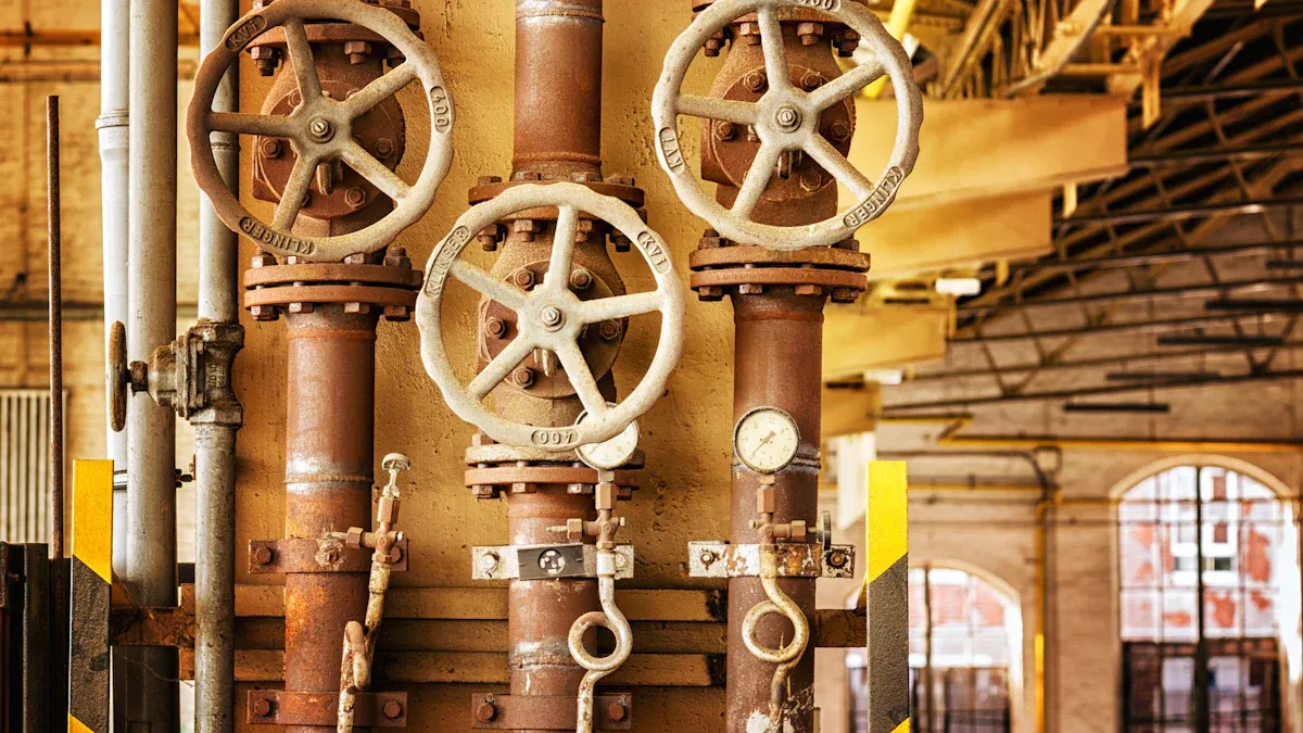
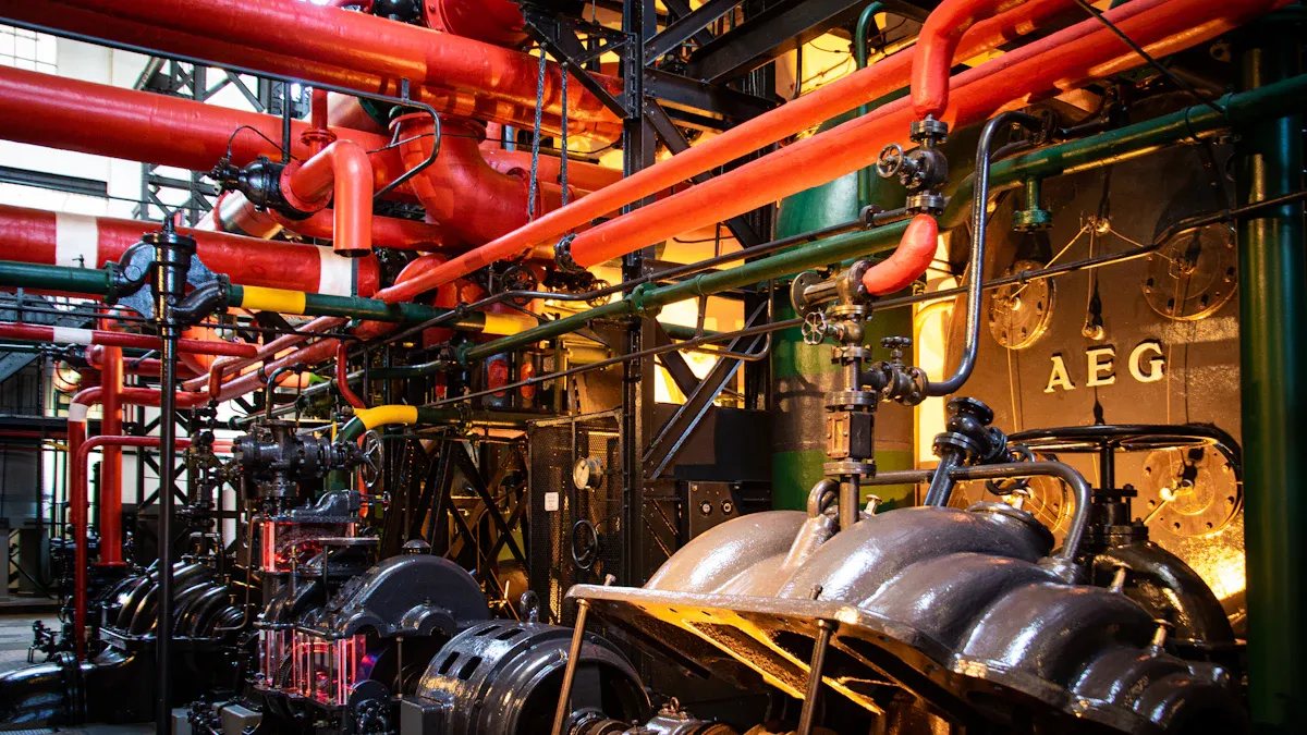
Solenoid Valve Type, Construction, and Material Selection
Direct, Semi-Direct, and Indirect Operated Solenoid Valves
Engineers choose from different solenoid valve types based on application needs. Each type operates differently. Direct-acting valves use the solenoid coil to directly move a plunger. This opens or closes the orifice. They do not need a pressure difference to work. Indirect-acting valves use a small pilot hole. Media pressure then moves a diaphragm or piston to open the main orifice. These valves require a minimum pressure differential. Semi-direct acting valves combine features of both. The solenoid provides mechanical force. Media pressure assists in lifting the diaphragm. They operate from zero pressure and handle high flow.
The table below highlights key differences:
| Valve Type | Operational Mechanism | Pressure Requirement | Flow Rate Capability | Key Applications |
|---|---|---|---|---|
| 2-Way Solenoid Valve | Opens or closes flow between inlet & outlet using electromagnetic coil | Requires minimum pressure differential (varies by design) | Medium to high flow | Water control, HVAC, irrigation, general automation |
| 3-Way Solenoid Valve | Directs flow between three ports; used for switching or venting | Typically low pressure; some models require no pressure differential | Low to medium flow | Pneumatic control, cylinder actuation, air systems |
| 4-Way Solenoid Valve | Controls double-acting cylinders with four flow paths | Requires stable compressed air supply | Medium flow | Industrial automation, pneumatic tools, machinery control |
| Pilot-Operated Solenoid Valve | Uses line pressure with a pilot orifice to assist opening/closing | Requires minimum operating pressure | High flow | Water supply, large pipe systems, high-flow industrial use |
| Direct-Acting Solenoid Valve | Coil directly lifts plunger without relying on line pressure | Works at zero pressure | Lower flow than pilot-operated types | Vacuum systems, low-pressure systems, precision dosing |
| Normally Closed (NC) | Valve stays closed without power; opens when energized | Depends on design (direct or pilot) | Medium to high | Safety shutoff, water & air control |
| Normally Open (NO) | Valve stays open without power; closes when energized | Depends on design | Medium flow | Cooling systems, fail-open applications |
| Proportional Solenoid Valve | Coil current controls valve opening proportionally | Requires stable supply pressure | Variable / controlled flow | Flow control, metering, industrial automation |
| High-Pressure Solenoid Valve | Reinforced structure for high-pressure media | Requires high inlet pressure | Medium flow | Hydraulic systems, pressure control, industrial machines |
| Cryogenic Solenoid Valve | Designed for extremely low temperatures | Varies by model | Medium flow | Liquid nitrogen, cryogenic gas systems |
. The best way to control these valves is to use a simple on/off control. This ensures that the valve opens and closes fully. This helps prevent partial opening or closing, which can cause issues.
Body Material for Solenoid Valve Durability**
The body material choice is crucial for valve longevity. It depends on the fluid properties and environmental conditions. Common materials include brass, stainless steel, and various plastics. Brass offers good strength and corrosion resistance for general applications. Stainless steel provides superior corrosion resistance, suitable for corrosive fluids or high-purity applications. Plastics offer cost-effective solutions for non-corrosive or low-temperature applications.
Seal Material Compatibility
Seal material compatibility is vital for preventing leaks and ensuring safe operation. The seal material must resist chemical attack from the fluid. It must also withstand the operating temperature and pressure. Common seal materials include NBR, EPDM, and Viton. NBR (Buna-N) works well with petroleum-based oils and water. EPDM is suitable for hot water and steam. Viton offers excellent chemical resistance, especially for fuels and aggressive chemicals. Choosing the right seal material prevents costly downtime and ensures system integrity.
Electrical and Environmental Considerations for Solenoid Valves
Voltage and Power Consumption
Correct voltage supply is essential for solenoid valve performance. Overvoltage can overheat and damage the coil. This leads to burnouts or insulation failure. Undervoltage may prevent the valve from fully actuating. This causes inconsistent behavior or “chattering.” Using voltage-stabilized power supplies helps maintain consistent electrical input. Surge protection devices also protect the coil from transients. Higher than rated voltage increases current. This leads to coil overheating, insulation damage, and reduced lifespan. Low voltage results in an insufficient magnetic field for actuation. High voltage causes overly quick or forceful actuation. This potentially leads to mechanical damage. Prolonged exposure to fluctuations causes insulation breakdown and short circuits.
AC solenoids initially draw high power for rapid activation. They then require less power to remain active. This makes them more energy-efficient over time. DC solenoids draw steady power. This can lead to higher overall energy use. They open valves more slowly. They maintain a constant current, potentially wasting energy. For DC solenoids, current consumption depends solely on the winding’s active resistance. After switching on, the current gradually increases until it reaches a constant holding current.
Ingress Protection (IP) Rating for Solenoid Valves
IP ratings, or Ingress Protection ratings, indicate the degree of protection an electrical equipment enclosure provides against solid particles and liquids. The International Electrotechnical Commission (IEC) developed these ratings. They use a two-digit code. The first digit (0-6) denotes protection against solid particles. The second digit (0-8) signifies protection against liquids.
| IP Number | Protection Against | Additional Details |
|---|---|---|
| IP0_ | No protection | Not protected against any ingress |
| IP1_ | Solid objects larger than 50mm | Blocks large body parts like a hand |
| IP2_ | Solid objects larger than 12.5mm | Blocks fingers or similar-sized objects |
| IP3_ | Solid objects larger than 2.5mm | Blocks thick tools, wires |
| IP4_ | Solid objects larger than 1mm | Blocks most wires, screws |
| IP5_ | Dust-protected | Limited ingress of dust; no harmful deposits |
| IP6_ | Dust-tight | Completely sealed against dust |
| IP Number | Protection Against | Additional Details |
|---|---|---|
| IP_0 | No protection | No water ingress protection |
| IP_1 | Vertically dripping water | Blocks vertically falling water drops |
| IP_2 | Dripping water when tilted up to 15 degrees | Blocks water drops when tilted up to 15 degrees |
| IP_3 | Spraying water | Blocks water spray up to 60 degrees |
| IP_4 | Splashing water | Blocks splashing water from any direction |
| IP_5 | Water jets | Blocks water jets from any direction |
| IP_6 | Powerful water jets | Blocks strong water jets |
| IP_7 | Immersion up to 1 meter | Protects against temporary water immersion |
| IP_8 | Continuous immersion beyond 1 meter | Suitable for continuous underwater use |
| IP_9K | High-temperature, high-pressure water jets | Protection against close-range, high-pressure, high-temperature sprays. |
Connection Standards and Ambient Conditions
Common electrical connection standards for these valves follow DIN standards. These include DIN EN 175301-803 Form A, Form B, and Form C. Previously, they were known as DIN 43650 Form A, Form B, or Form C. Valves in hazardous applications should meet standards from organizations like the National Fire Protection Association (NFPA) in the United States and the International Electrotechnical Commission (IEC). Other important international standards include IEC 60079 for explosion-proof equipment and ANSI/NFPA 70 (National Electrical Code – NEC) for electrical installations. CE marking indicates compliance with EU health, safety, and environmental protection standards.
Harsh operating conditions shorten a valve’s life. Exposure to extreme temperatures is one such condition. High humidity is another environmental factor that reduces the valve’s lifespan. The qualified life of a Solenoid Operated Valve (SOV) depends on various factors. These include ambient environment temperatures, pressures, and relative humidity. Exposure to temperature critically affects the aging of an SOV. Thermal aging is influenced by ambient temperatures. Every material in an SOV has an ‘activation energy’ that dictates its aging characteristics. This is especially true for non-metallic components. Thermal aging occurs through radiation, convection, and conduction. The coil itself generates heat. This heat dissipates to all components within its enclosure, contributing to thermal aging.
A comprehensive evaluation of all factors is vital for optimal solenoid valve selection. Engineers must match the valve to specific application needs. This ensures long-term performance and safety. Prioritizing compatibility, operational demands, and correct sizing leads to successful system integration. This careful process prevents failures and optimizes system efficiency.
FAQ
What media can a solenoid valve handle, and why does media type matter?
The type of fluid (water, air, oil, gas, steam, chemicals) affects the valve material, seal type, and internal structure. For example, brass valves suit water and air, while stainless steel or PTFE seals may be required for corrosive or high-temperature media.
How do pressure and flow requirements influence solenoid valve selection?
Solenoid valves differ in minimum operating pressure, maximum pressure rating, and flow rate capacity. Some require a pressure differential (pilot-operated), while direct-acting valves work at zero pressure. Understanding system pressure ensures stable opening/closing and prevents leakage or failure.
What is the difference between Normally Open (NO) and Normally Closed (NC) solenoid valves?
A Normally Closed valve stays shut until energized; an NC type is used for safety shutoff or water control. A Normally Open valve remains open without power and is used in fail-open or cooling systems. Choosing NO vs. NC depends on the fail-safe behavior your application requires.
Does valve response time affect performance?
Yes. Applications requiring fast switching—such as pneumatic automation or dosing systems—need solenoid valves with millisecond-level response times. Slow response can lead to poor control accuracy or equipment damage.
How do environmental conditions impact the type of solenoid valve I should choose?
Temperature, humidity, dust, vibration, and exposure to chemicals determine coil insulation, sealing grade (IP rating), and body materials. Outdoor or industrial environments may require waterproof coils, explosion-proof designs, or corrosion-resistant housings.